it
Di seguito viene mostrato un esempio passo passo della composizione di una rete multi-dataflow da parte di MDC e del suo mapping in una piattaforma hardware riconfigurabile.
Passo 1
In input si hanno due reti dataflow (NET1 in verde e NET2 in blu) con alcuni attori comuni, nell’esempio l’attore C e l’attore E.
Passo 2
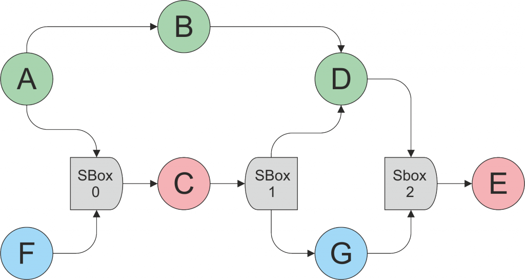
A partire dalle due reti in ingresso viene generata una rete multi-dataflow in cui gli attori comuni, C e l’attore E, sono condivisi (in rosso) tramite le SBox (in grigio).
Passo 3
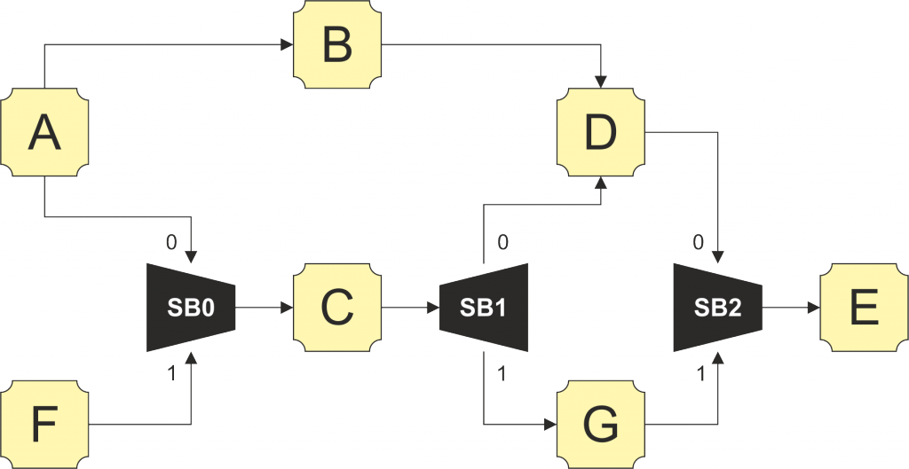
La rete multi-dataflow viene mappata nella corrispondente specifica HDL, istanziando i componenti della libreria (in arancio) che corrispondono ai diversi attori dataflow. Le SBox sono implementate da dei multiplexer e dei demultiplexer. La configurazione viene memorizzata in delle apposite Look-Up Table.
| LUT | SB1 | SB2 | SB3 |
| NET1 | 0 | 0 | 0 |
| NET2 | 1 | 1 | 1 |
en
Here follows a step-by-step example of the composition of a multi-dataflow network and of its mapping on a coarse-grained reconfigurable hardware platform.
Step 1
Two dataflow networks (NET1 and NET2 respectively in green in blue) are the input specifications and present some common actors: the actor C and the actor E.
Step 2
Starting from the two input networks a multi-dataflow network is generated, where the common actors (C and E) are shared (in red) through Sbox elements (in gray).
Step 3
At last, the multi-dataflow network is mapped in the corresponding HDL code, instantiating all the components (in orange) that correspond to the different dataflow actors from the library of components. The Sbox modules are implemented as multiplexer and demultiplexer units. The configuration is stored in the dedicated Look-Up Table.
| LUT | SB1 | SB2 | SB3 |
| NET1 | 0 | 0 | 0 |
| NET2 | 1 | 1 | 1 |


